GEOTECHNICAL ENGINEERING
OKLAHOMA CITY
HomeGeophysicsSeismic tomography (refraction/reflection)

Seismic Tomography (Refraction and Reflection) in Oklahoma City

Evidence-based design. Reliable delivery.

LEARN MORE

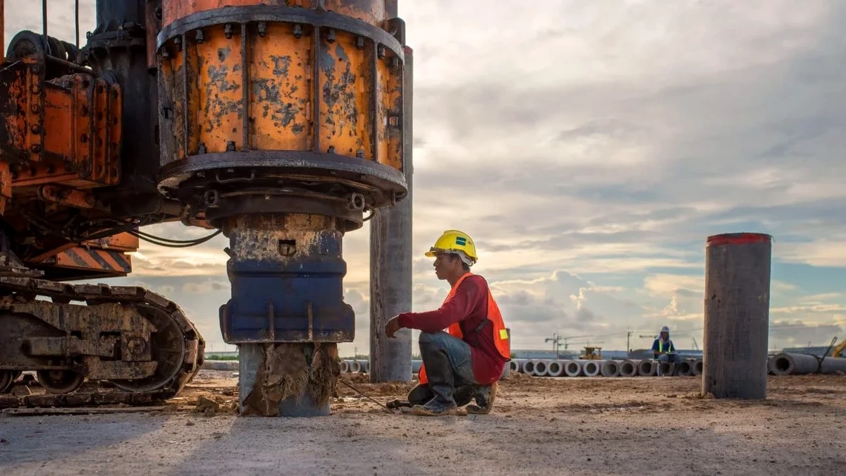
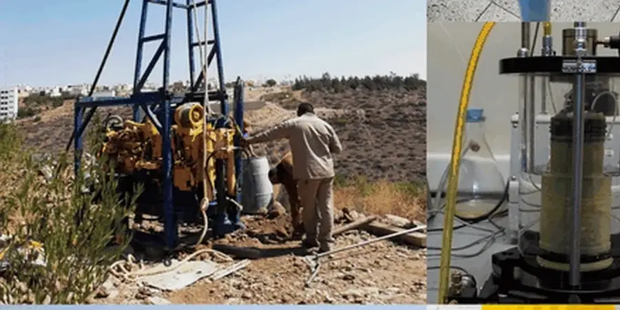
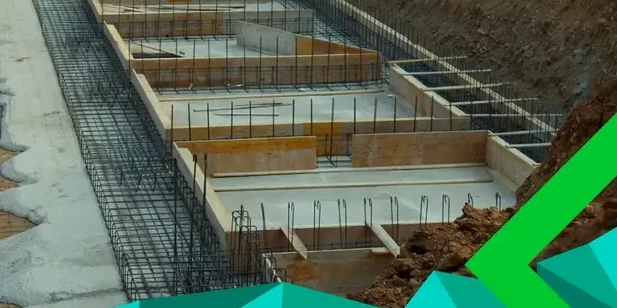
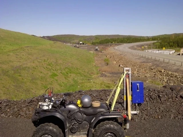
Oklahoma City's expansion from the Land Run of 1889 into a sprawling metro area of nearly 700,000 residents has placed heavy demands on subsurface investigation. The city sits atop a complex sequence of Permian red beds — interbedded shales, siltstones, and sandstones — overlain in many areas by Quaternary alluvium along the North Canadian River. What complicates matters here is the differential weathering profile: competent sandstone ledges can grade laterally into fully softened shale within a few hundred feet, a transition almost invisible from the surface but critical for foundation design. We routinely deploy seismic refraction and reflection tomography to resolve these transitions before a single auger hits the ground. The method sends acoustic waves into the subsurface and measures their travel times along geophone arrays, generating velocity models that map stratigraphy, estimate rippability, and flag anomalous low-velocity zones that often indicate paleochannels or dissolution features within the Garber-Wellington aquifer system. For deeper targets — such as verifying bedrock integrity beneath proposed bridge piers along I-35 or I-40 — reflection profiling provides a higher-resolution image of layer geometry, complementing the velocity data with true structural section views.

A single seismic line can map bedrock topography across an entire site in half a day — something that would take a week of test pits to piece together.

Our service areas

Process and scope

The near-surface geology across Oklahoma County presents a textbook case for seismic tomography. Much of the city rests on the Garber Sandstone and Wellington Formation, where alternating sandstone-shale sequences create strong acoustic impedance contrasts that reflect seismic energy cleanly. In our experience, the water table — typically encountered between 15 and 30 feet depth in the alluvial corridors — acts as an excellent refractor, allowing us to map the saturated zone with repeatable accuracy. We set up 24- or 48-channel geophone spreads with hammer or accelerated weight-drop sources for shallow targets, switching to a larger seismic source when we need penetration beyond 100 feet. The resulting P-wave and S-wave velocity sections feed directly into site classification per ASCE 7 and IBC seismic provisions, providing the shear-wave velocity (Vs30) data required for seismic design category determination. Where the scope includes pavement design or slab-on-grade performance, we often combine seismic tomography with a CBR field test to correlate stiffness profiles directly with bearing capacity. In karst-prone areas along the eastern edge of the city, microgravity anomalies can be cross-checked using electrical resistivity profiling, which discriminates air-filled voids from clay-filled depressions that seismic velocities alone cannot always separate.
Seismic Tomography (Refraction and Reflection) in Oklahoma City
Technical reference — Oklahoma City

Local geotechnical context

Our Oklahoma City field crew runs a 48-channel Geometrics Geode seismograph paired with 4.5 Hz geophones — a setup we calibrate on a reference concrete pad before every survey to verify trigger timing and channel-to-channel amplitude consistency. On a hot August afternoon when surface temps hit 105°F, the biggest threat is not the heat itself but the thermal expansion of the spread cables, which can introduce microsecond-level timing drift if they are not staked down properly. We lay the cables under tension and check coupling by hammer-tapping each geophone position while watching the real-time shot gather; a loose geophone on dry, sun-baked clay produces a telltale low-frequency ringdown that any trained observer catches immediately. Wind above 20 mph is another hazard — it generates coherent noise in the 10-30 Hz band that overlaps with deep-refraction arrivals, so we schedule long-offset shots for early morning when the Oklahoma wind tends to settle. Skimping on source energy to save mobilization time is a false economy: an underpowered shot on a thick alluvial section simply fails to generate a first-arrival from the bedrock refractor, leaving the interpreter with an ambiguous velocity model and a foundation designer guessing at depth-to-rock.

Need a geotechnical assessment?

Reply within 24h.

Email: contact@geotechnical-engineering.xyz

Applicable standards

ASTM D5777 — Standard Guide for Using the Seismic Refraction Method, ASTM D7128 — Standard Guide for Using the Seismic Reflection Method, ASCE 7-22 — Minimum Design Loads and Associated Criteria for Buildings and Other Structures (Vs30 site classification), IBC 2021 — International Building Code (Seismic Design Category determination), FHWA HI-99-007 — Geophysical Methods for Highway Applications

Technical parameters

ParameterTypical value
P-wave velocity range (competent sandstone)6,000–12,000 ft/s
S-wave velocity (Vs30) — typical OKC alluvium600–1,200 ft/s
Maximum investigation depth (refraction)100–150 ft (dependent on source energy)
Typical geophone spacing5–10 ft (24- or 48-channel array)
Source type (shallow targets)Sledgehammer or 100-lb weight drop
Seismic design category inputVs30 profile per IBC/ASCE 7
Data processing softwareSeisImager, Rayfract, or equivalent
Reporting standardVelocity tomograms with interpreted geologic cross-sections

Common questions

How deep can seismic refraction see in Oklahoma City's geology?

Depth penetration depends on source energy and the velocity contrast between layers. In Oklahoma City, where we work across Garber Sandstone and Wellington Formation sequences, a sledgehammer source typically resolves refractors down to 40-60 feet, while an accelerated weight drop or elastic-wave source can push first arrivals to 100-150 feet. The key limitation is the velocity inversion problem: if a soft shale underlies a harder sandstone ledge, the refraction method may miss it entirely. That is precisely why we cross-reference seismic data with available boring logs and, when necessary, supplement with reflection profiling or other geophysical methods.

What does a seismic tomography survey cost in the Oklahoma City area?

For a typical site in the Oklahoma City metro, seismic refraction or reflection surveys generally range from US$2,660 to US$5,060, depending on the number of geophone channels, the length of the spread, the source type required, and whether we are acquiring P-wave only or both P-wave and S-wave data. Projects that require traffic control along busy corridors like NW Expressway or I-240 add mobilization complexity that influences the final figure. We provide a detailed scope and fixed-price proposal after reviewing site conditions and project objectives.

How does seismic tomography compare to drilling for site characterization?

They answer different questions and work best together. A boring gives you a point measurement — exact soil type, blow counts, and moisture content at one location. Seismic tomography gives you a continuous cross-section of velocity between boreholes, revealing what happens in the gaps. In Oklahoma City's interbedded Permian formations, a sandstone channel can pinch out between two borings spaced 100 feet apart; seismic velocity data catches that lateral discontinuity and allows the geotechnical engineer to decide whether additional borings are warranted. The combination of direct sampling and geophysical imaging consistently produces the most defensible ground model.

Location and service area

We serve projects in Oklahoma City and surrounding areas. More info.

View larger map